Binary Decision Diagrams (BDDs) are a powerful data structure used in computer science and engineering to represent and manipulate Boolean functions efficiently. They are particularly useful in areas such as formal verification, hardware design, and software analysis. This article provides an in-depth overview of BDDs, their types, operations, and applications.
NIST defines Binary Decision Diagram (BDD) as “A binary lattice data structure that succinctly represents a truth table by collapsing redundant nodes and eliminating unnecessary nodes.”
A BDD (Bryant 1986) or branching program is a data structure that is used to represent a Boolean function. On a more abstract level, BDDs can be considered as a compressed representation of sets or relations. Unlike other compressed representations, operations are performed directly on the compressed representation, i.e. without decompression. A BDD represents a Boolean function as a rooted directed acyclic graph (DAG), which consists of several decision nodes and terminal nodes. Many logical operations on BDDs can be performed such as conjunction (Logical AND operation), disjunction (OR Operation) and negation (NOT Operation).
The term BDD mostly refers to Reduced Ordered Binary Decision Diagram (ROBDD in the literature, used when the ordering and reduction aspects need to be emphasized). The advantage of an ROBDD is that it is canonical (unique) for a particular function and variable order. This property makes it useful in functional equivalence checking and other operations like functional technology mapping.
Table of Contents
- What is a Binary Decision Diagram?
- Types of Binary Decision Diagrams
- Applications of BDDs
- Binary Decision Diagram Example
- Tools and Libraries for BDDs
What is a Binary Decision Diagram?
A Binary Decision Diagram (BDD) is a directed acyclic graph (DAG) that represents a Boolean function. Each node in the graph corresponds to a decision variable, and the edges represent the possible outcomes of the decision (typically 0 or 1). The leaves of the graph represent the final output of the Boolean function (either True or False).
Key Features of BDDs:
- Compact Representation: BDDs can represent large Boolean functions in a compact form by sharing common subgraphs.
- Canonical Form: Reduced Ordered Binary Decision Diagrams (ROBDDs) have a unique representation for a given Boolean function, making them ideal for equivalence checking.
- Efficient Operations: BDDs support efficient Boolean operations such as AND, OR, NOT, and existential quantification.
Types of Binary Decision Diagrams
1. Ordered Binary Decision Diagrams (OBDDs):
In OBDDs, the decision variables are evaluated in a fixed order. This ordering ensures that the structure of the BDD remains consistent, which is crucial for efficient manipulation.
2. Reduced Ordered Binary Decision Diagrams (ROBDDs):
ROBDDs are a canonical form of OBDDs where redundant nodes and isomorphic subgraphs are eliminated. This reduction makes ROBDDs highly efficient for practical applications.
3. Zero-Suppressed Binary Decision Diagrams (ZDDs):
ZDDs are a variant of BDDs optimized for representing sparse sets of combinations. They are particularly useful in combinatorial problems.
4. Free Binary Decision Diagrams (FBDDs):
FBDDs do not enforce a fixed variable ordering, making them more flexible but less efficient for certain operations.
Applications of BDDs
BDDs have a wide range of applications in computer science and engineering:
- Formal Verification: BDDs are used in model checking to verify the correctness of hardware and software systems.
- Hardware Design: BDDs help in the synthesis and optimization of digital circuits.
- Software Analysis: BDDs are used in static analysis tools to detect bugs and vulnerabilities in software.
- Combinatorial Optimization: ZDDs, a variant of BDDs, are used to solve problems involving combinations and permutations.
- Artificial Intelligence: BDDs are used in knowledge representation and reasoning systems.
- Computer-aided design: BDDs are mainly used in Computer-aided design software for logic synthesis.
Binary Decision Diagram Example

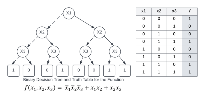
The figure above shows a binary decision tree (the reduction rules are not applied), and a truth table, each representing the function f (x1, x2, x3). In the tree on the left, the value of the function can be determined for a given variable assignment by following a path down the graph to a terminal. In the figures below, dotted lines represent edges to a low child (0), while solid lines represent edges to a high child (1). Therefore, to find (x1=0, x2=1, x3=1), begin at x1, traverse down the dotted line to x2 (since x1 has an assignment to 0), then down two solid lines (since x2 and x3 each have an assignment to one). This leads to the terminal 1, which is the value of f (x1=0, x2=1, x3=1).
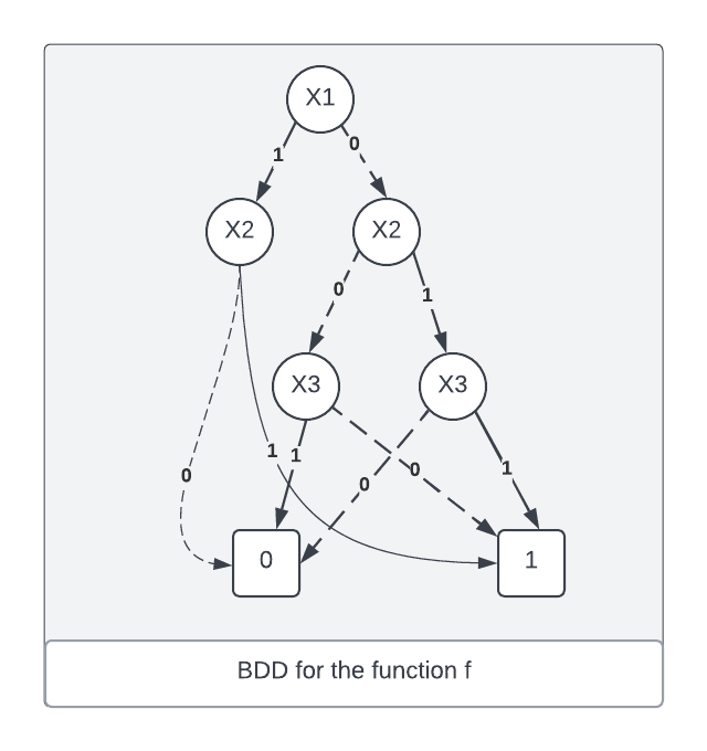
The binary decision tree of the figure above can be transformed into a binary decision diagram by maximally reducing it according to the two reduction rules. The resulting BDD is shown in the figure as below.

There are many other advance data structures you can use in solving your complex problems. For example, Trie data structure is mainly used for sorting. Binary Trees are mainly used for searching and sorting as they provide a means to store data hierarchically.

Unlock the world of programming with C++ for Dummies – the perfect beginner’s guide to mastering C++ with ease and confidence!
View on Amazon
Tools and Libraries for BDDs
Several tools and libraries are available for working with BDDs:
- CUDD (Colorado University Decision Diagram Package): A popular library for manipulating BDDs and ZDDs.
- BuDDy: A lightweight BDD library for C++.
- PyEDA: A Python library for electronic design automation, including BDD support.
- JavaBDD: A Java-based library for BDD manipulation.


